New Drilling Technique (Nitrogen Cap Drilling, NCD).
Recently has been implanted a new drilling technique very different, in which the drilling fluid pumped through the drill pipe doesn’t return to the surface, it is lost to the formation. In the annulus (Drill pipe- Casing, Drill Pipe – Formation) a very viscous fluid is placed (it doesn’t circulate) and an appropriated amount of nitrogen is pumped above this fluid to keep the annular hydrostatic pressure balanced with the formation pressure.

The NCD concept is inject nitrogen into a “nitrogen cap” or bubble above a static column of mud. Monitoring of the surface pressure combined with an accurate fluid level monitoring in the annulus with an Echometer will allow estimating precisely the bottomhole pressure. Additional mud can be pumped (periodically or continuously) as needed, or additional nitrogen can be injected to adjust pressure in the annulus if a pressure drop is observed or additional pressure and volume is needed to stabilize the annulus. The ability to monitor the fluid level or pressure profile in the annulus allows, during drilling operations, identify and react to any changes on pressure.
At this point, the acoustic surveys (Echometer Technology) are required to monitoring the interface between the “nitrogen cap” and the “viscous drilling fluid” in the annulus, due to this parameter (Fluid level) associated with the casing head pressure (CHP) would be early stage indicators of unexpected hydrocarbons influx or circulation lost.
Equipment required for Acoustic Measurement.
This technical note describes an Acoustic Fluid Level Monitoring System that operates without drilling fluids circulation or the annulus being full of drilling fluid.
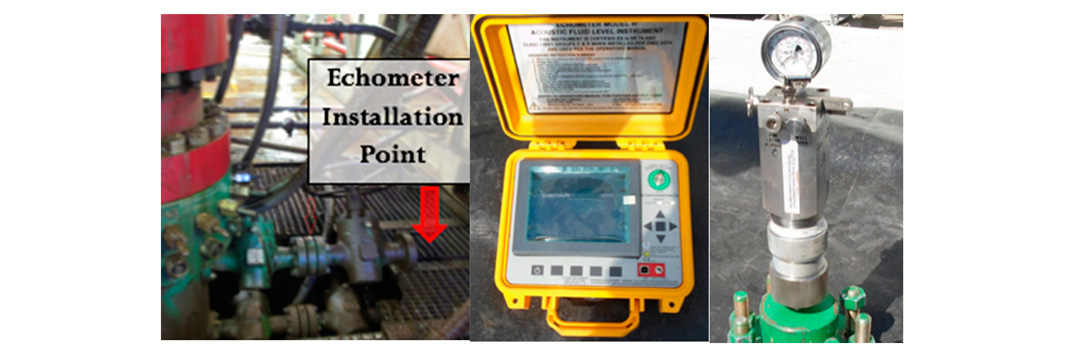
Two equipments are required. A Gas Gun (Compact in this case) which has two functions, first create an acoustic pulse at the surface that travels through the wellbore (Annulus), and the second function that is made by a microphone housed in the gas gun, is receives, amplifies, filters and converts into electrical signals the echoes reflected by collars, obstructions or the fluids level.
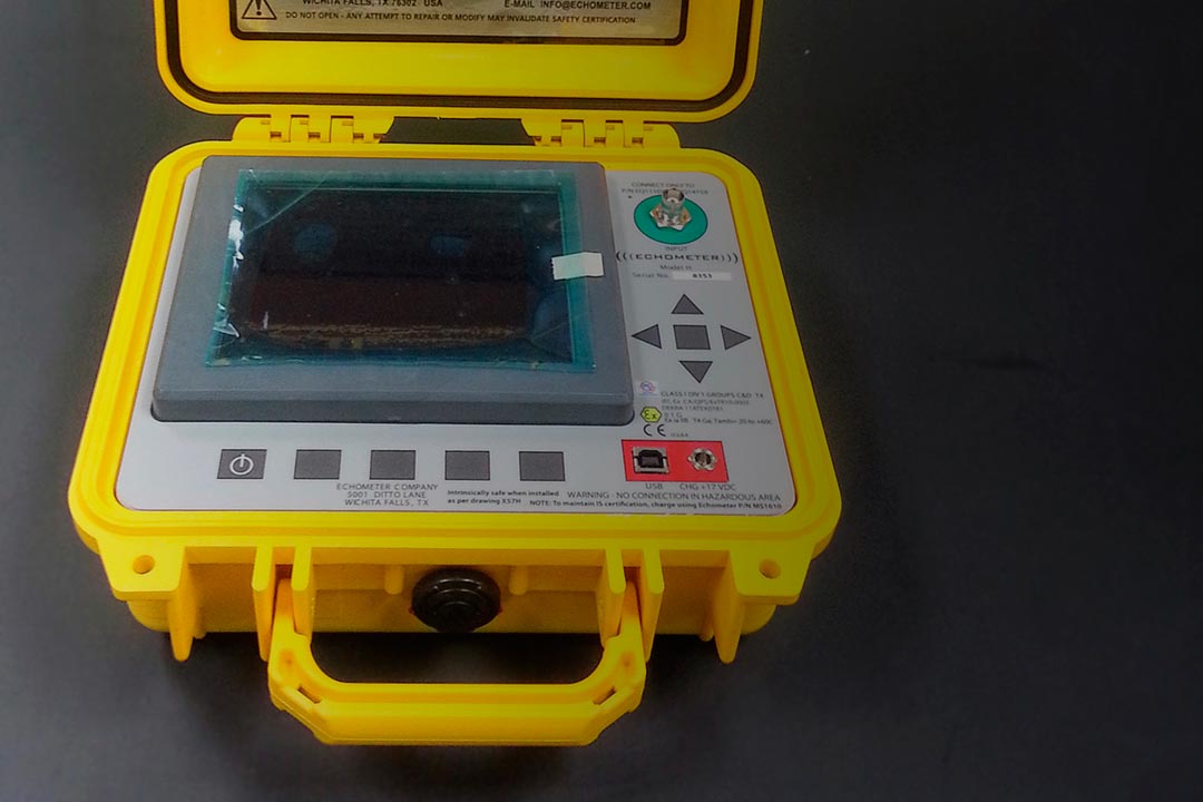
The other equipment is the Echometer well analyzer (Model H) that process the electrical signals and generated an acoustic trace that could be visualized on the equipment screen, this equipment can also stores the information. The Model H is capable of automatic selection of the liquid level reflection by a pattern recognition scheme that involves the amplitude, polarity, width, and phase shift of the received signals. The software scans the digitized record and selects all the signals and the pattern requirements, then selects the most probable to present to the operator. The computerized processing of the acoustic trace have resulted in significant advances and improvements in acoustic well sounding, that provide more accurate liquid level depths and allows real-time visualization of the wellbore conditions.
Rig Facility.
Additional to rig conventional equipment some others must be added to carry out the NCD, some of this equipment are: Nitrogen Source, Booster (inject nitrogen), fluid level monitoring system, wellhead pressure and temperature gauge, choke manifold, downhole barrier valve, , gas sensor, RCD rotational control device (Equipment required to seal the drilling system and permit to create the cap of nitrogen).
NCD and Acoustic Measurements fingerprinting.
The fingerprinting is the process whereby the acoustic measurement and the NCD bubble are characterized and calibrated, this was done in cased hole (intermedia casing) as follows:
- Trip in hole and tag cement. Shut down trip tank pump.
- At the well head under the BOP, one of casing arm was used to Hook up Echometer (fluid level measurement device).
- Without the trip tank pumps running and prior to pumping nitrogen, pull out of hole twenty (20) dry stands, this will cause an annular void space. Measure the fluid level drop in the annulus using the Echometer every 5 stands.
- Finally to evaluate the performance of the acoustic survey; the liquid level depth determinate with the acoustic survey and the calculated distance to the liquid level drop in the annulus occurred by pulling out of the hole for dry drill pipe stands (drill pipe displacement) were compared.
Operation.

After the NCD and the acoustic measurement were fingerprinting, the interest zone was began to drill. Using the compact gas gun attached to the well head, during normal operations an acoustic reading was took every stand for the first ten (10) stands, then every three (03) stand.
If drilling operation require tripping in or tripping out the drill pipe, an acoustic reading was took every stand for the first five (05) stand, and then every three stand.
The change of the RCD element was considered a critical condition; hence every time that the element must be change, an acoustic reading must be taken every three minutes.
Another critical situations was presented during logging operation, since there were no drill pipe inside the wellbore, and almost all the nitrogen was bleed off (CHP @ 0,0), therefore the hydraulic connections with the bottom of the hole was limited, and this may have made detection more difficult the detection and control of any influx or loss of drilling fluid to the formation, so the acoustic measurement was the only tool to monitoring the hydrostatic pressure profile inside the wellbore, during this type of operations an acoustic measurement was take every five minutes.
Acoustic Trace Analysis.
The deflection of the liquid level didn’t show a habitual behavior (Upward downward deflection), instead a series of undulations in the acoustic trace were visualized, and the liquid level must been defined and verified through its repetitions.
Since the initial blast necessary to create the acoustic pulse normally affected the first half second (1/2 seg) of the acoustic trace and most of the liquid level were shallow (less than one second), inhibited the use of technique named “Collar Count” to determinate the distant to the liquid level.
Discussion of Results, lessons learned.
- The measurement of liquid levels during drilling operations applying the NCD is accurate, deviations less than 8% between the Fluid Levels determined with Echometer and those calculated with the displacement of fluids from the pipe.
- This drilling / monitoring technique has been successful in all the wells, a total of 05 wells from June 2,017 to January 2,018. Successful wells are those which the Interest Zone (Reservoir) was drilled entirely without operational drawbacks.
- It was possible to detect fluid levels with an Echometer mounted on the wellhead, while wasn’t pumped fluid in the annulus (or only intermittently pumped).
- The Echometer wasn't capable to detect acoustic readings while mud was pumped into the annulus, since the sound waves will reflect off the slugs of mud as they are falling.
- Mechanical noise during drilling operations or tripping in and out of the hole didn’t affect liquid level detections.
- During the wireline operations the energy of the shot is divided because there is no seal above the sonolog valve (casing valve), a part of the energy travels upstream and a portion of the energy travels downstream. Therefore the acoustic trace was carefully analyzed to discriminate between the deflection of the liquid level and deflection created by energy of the acoustic pulse that travels upward to the top of the lubricator, this deflection is equivalent to the distance from the wellhead (Ground) to the top of the lubricator installed with the wireline equipment.
- If the wellhead pressure reach 0.0 psig (In case of venting the nitrogen completely), it is necessary pump some nitrogen to create a means of propagation for the acoustic pulse.