MSc. Sergio Caicedo
Artificial Lift Expert at UPC Global
Introduction
There are many Electro Submersible Pumping (ESP) wells continuously growing with a significant percentage of global oil production, however, it is amazing the large number of misconceptions that still exist related with this equipment.
Based on a misconception there is the possibility of having an over-expectation and therefore the decision is made to use an ESP in a well and then face with the operational reality whose conditions make it impossible to achieve the production target and/or to achieve an acceptable run life. The opposite may also happen, that the prediction is very pessimistic therefore the ESP is not installed, but then studying experiences of other colleagues from other companies we learn of successful field tests under the same conditions. It is for this reason it is very important to understand how these equipment work because the decision to employ or discard them are based on misconceptions or misunderstood communications between management and engineers.
Among the misconceptions commonly related with ESP are the following
- ESP delivers pressure in a manner analogous to Sucker Rod Pump and PCP.
- Critical variables for each equipment component are understood.
- The pump will produce its capacity at the operating frequency.
- A high gas-to-oil ratio GOR rules out the use of ESP.
- With the available field experiences, it is possible to make conclusions and definitive decisions.
- The decision is economically justified.
- The ESPs are always associated with high electricity consumption (HP KVA)
- The most influential variables in the production process with ESP are clearly identified.
- High viscosity corrections are simple.
- Surveillance consists of acquiring and monitoring the variables.
- Operational practices of other methods are applicable.
In this article we will discuss each of these to show both at the managerial and engineering level the need to fully understand the operating principles of each of the components of the ESP in order not to have erroneous expectations either because they are overly optimistic or pessimistic.
ESP delivers pressure in a manner analogous to Sucker Rod Pump and PCP.
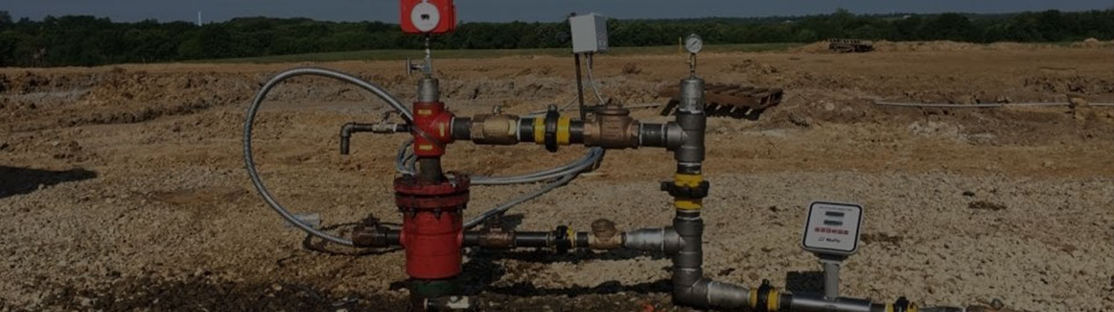
SPEs are multi-stage centrifugal pumps (hundreds of stacked stages) and the way they pump is by providing kinetic energy that is then transformed into pressure, this concept must be understood for both its design and its field operation. The expected flow rate of the ESP-Reservoir system is not a simple relationship where increasing frequency will always get more production proportionally. There are phenomena that govern and limit the system, such as: pumping capacity (pressure vs. flow) with speed, power increase, fluid level at the intake, reservoir gas release, motor limitation, etc.
Keep in mind that the ESP completion includes motor, protector, downhole gas separator, pump, cable and variable
frequency driver. A wrong selection or sizing, or improper operation of any of these components will result in below expected performance and premature equipment failure. Considering an ESP simply as a pump without understanding how this system works together and interacts with the reservoir is an error that will not allow you to obtain a feasible production and according to the ESP-reservoir system, nor an acceptable run life.
On the other hand, the most used downhole motor is the induction and recently they are starting to use permanent magnet motors (PMM). Understanding the power requirements imposed by the centrifugal pump on the engine and how the engine works is very relevant for design, analysis, and operation.
The main consequence of this disconnection is to install or operate inappropriate ESP equipment, such as:
- Pumps with excessive flow capacity but insufficient pressure gain.
- Pumps with excessive pressure capacity, but oversized or undersized in flow.
- Motor oversized or undersized in power with a proper selected pump.
- Inadequate selection of protectors despite proper motor and pump.
- Cable selected only by amperage without considering downhole temperature.
- Improper Step-up transformer configuration.
Once a poorly designed ESP equipment is installed there is little chance to optimize its operation since the room for maneuver is very narrow or null, from there the importance of having equipment that allows to have as much flexibility as possible. It should be mentioned that a poorly selected pump and/or motor involves higher power consumption (and therefore production cost) to achieve the same or lower production rate.
Critical variables for each equipment component are understood.
By not understanding in detail the principle of operation of the components of an ESP system and the way in which they are interrelated has as consequence to ignore critical variables and their limit values. For example, for a given installation the critical parameter could be the pump shaft and due to unawareness only the motor temperature is being monitored, which will not generate any alarm for the protection of the pump shaft. Another case may be submergence, which can be very low despite having a relatively high pump intake pressure, so the inlet pressure alarm might in some cases not considering the submergence and the pump could run out of liquid level which is known as pump off condition.
One of the most common misunderstood parameters is well’s production rate, which while it may be within what was expected by the reservoir engineer could be outside the ESP's operating range which is reflected in low energy efficiency (high power consumption) and shorter run life. This problem is most common in light crudes (API > 40) and low water cut as oil volumetric factors involve 30% or more bottomhole volume compared to surface.
The presence of free gas in the pump is a special case that will be discussed in detail later, but the most complicated thing about this case is that there is no measuring device for this magnitude so it must be calculated, sometimes you have symptoms of the problem in the surface amperage consumption, but when it is detected it is possible that the pump is already blocked by gas. In addition, depending on the stage model and completion used the problem may be severe.
The pump will produce its capacity at the operating frequency.
One of the most common false beliefs that exist is that if an ESP whose stage model is for 5000 BPD is installed (see Figure 1) operating at 60Hz and the well is currently at that frequency then the well is producing 5000 BPD.
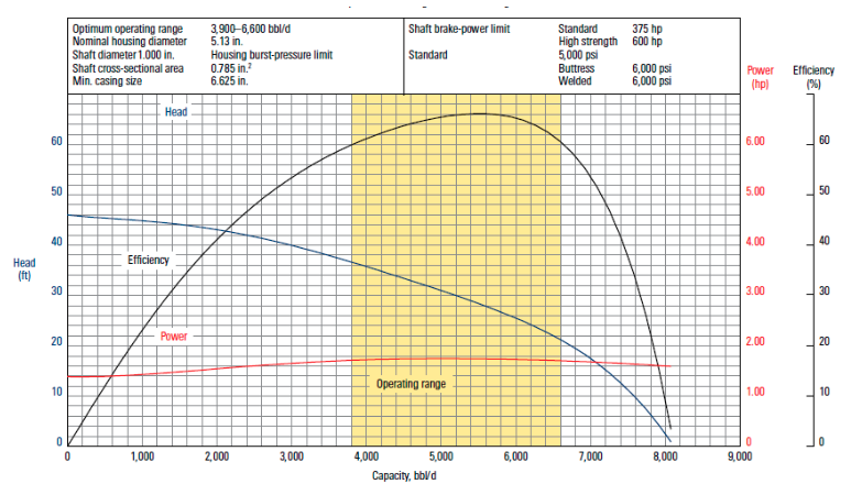
Fig 1. Example of Head, Power and Efficiency curves for a 5000BPD Nominal stage
Centrifugal pumps have a performance that relates the pressure gain (or head) versus the total in situ flow rate. The pump has a possible physical range ranging from 0 BPD (corresponding to the pressure gain of 19 psi or maximum head 45 ft for one stage) to maximum flow rate 8,000 BPD (as shown in Figure 1 corresponds to the maximum possible flow corresponds to zero pressure gain or head). However, although these values are feasible these values are not in the recommended range which in this example is from 3800 BPD to 6400BPD being 5400BPD the nominal flow as it is where there is the highest energy efficiency (of the mechanical energy provided by the motor on the shaft approximately 65% is transferred to the fluid). As the pump can produce in a range then the production flow in the field will be the one that stabilizes the system, which is according to the number of stages installed, the tubing diameters and depths, as well as the reservoir inflow curve. Therefore, if the same pump model is installed in two wells operating at the same frequency, but having some difference in number of stages, completions (diameters-depths) and reservoir inflow (productivity index and reservoir pressure) then different production and power consumption would be obtained. In addition, it should be noticed that the pump can produce only the capacity of the reservoir, that is, if the reservoir can at most produce 1000 BPD, installing a 5000 BPD pump will not cause the well to produce more than 1000 BPD, in fact this oversized pump will present problems of low fluid level (pump off) and shut down frequently.
High oil gas ratio rules out use of ESP
It is usually mistakenly thought that having a high oil gas ratio (>1000 SCF/BBL) makes impossible to use an ESP or having a low oil gas ratio (200 SCF/BBL) makes possible to use an ESP. Both claims may not be true as the other variables affecting the percentage of free gas may increase or decrease their value as explained below.
All pumping systems are somehow affected by free gas, the first effect that gas has on pumps is that the gas will occupy a space, which requires considering greater pumping capacity in the design. For example, if we need to produce 2000 BPD
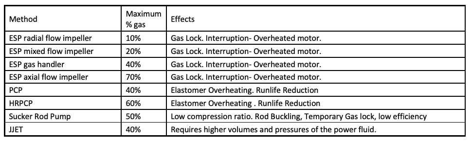
having 50% free gas at pump intake conditions, then the pump should be sized for 4000 BPD regardless of whether it is ESP, PCP, SRP, JET. Second, each method has its own free gas handling limit and different effects as shown in Table 1.
Being the ESP system the most susceptible because the downhole motor could burn-out above by overheating which implies a workover to replace the equipment.
Table 1. Gas effects of gas on different pump types
The free gas percentage (%) also known as Gas void Fraction VGF, should not be confused with the liquid gas ratio or the oil gas ratio (GOR). While it is true that free gas depends on the oil gas ratio (GOR) it is also false that it depends only on this parameter. It should be noticed that the free gas depends on the following six 6 values: Pump Intake Pressure (PIP), Pump Intake Temperature (TIP), Oil Gas Ratio (GOR), Gas in Solution at Pump Intake (RS), Water Fraction (FW), and downhole gas Separation Efficiency before the pump. The percentage of free gas cannot be measured directly and can only be estimated with the following equation:
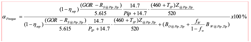
Estimating the percentage of free gas requires good knowledge of PVT to predict solution gas (RS) at Pip, Tip, and good knowledge of the downhole gas separation model is required. Keep in mind that even with high downhole gas separation efficiencies of 85% to 90% (which is not always achieved as it will depend on the casing size and the flow rates handled) this may not be enough to solve the problem in some cases.
The result of the equation for the percentage of free gas should be compared to the limit of the lifting system, if it is higher than the pump would have problems otherwise it is feasible to operate from the gas point of view.
In the ESP case note that there are different limits depending on which equipment is being used, but the most common and traditional are radial and mixed impellers that have low capacity (10% and 20% respectively) while gas handlers and axial impellers have more capacity (40% and 70% respectively) but there are fewer wells worldwide. It is important to know that there are different limits as what could have been a failed experience that vetoed the use of ESP in a field due to a mixed stage pump, could be transformed into a successful application if a pump with axial stages is used.
The fact that the free gas depends on the pump’s intake pressure has implications for the operation itself, that is, it could happen that the percentage of gas is manageable at low flow rate, but when increasing the frequency results in gas
interference problems. Visualizing where we are operating about free gas is vital for ESP monitoring and operation, but how to use this equation in monitoring is not easy, however, by including the concept of EIPR (Enriched inflow Performance relationship) we can clearly see an alarm associated with the intake pressure that considers the reservoir inflow performance while viewing the free gas together with the expected flow rate. In the EIPR shown in Figure 2 the color scale of the points indicates the percentage of free gas, which allows to visualize the effect of the pump depth and flow rate.
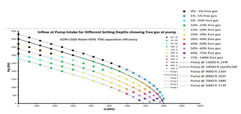
Fig. 2. EIPR curves at different pump depths showing free gas percentage % in color scale
Therefore, if the EIPR curve in Figure 2 was calculated considering the pump’s depth, the water cut, the Gas Oil Ratio GOR, and the downhole gas separation efficiency in the field (estimated or assumed), then it would give us a reference (Set
Point) for the minimum pressure that our pumping equipment can handle depending on the free gas handling limit. In this example it is seen that if the pump is installed at 6000 feet (green segmented line) you will have at least 5% gas for a very low flow rate and approximately 30% for 4000 BPD and more than 75% for 7000 BPD maximum production for that pump depth, while at approximately 10000 feet there is no free gas to pump inlet conditions up to approximately 3000 BPD; 10% to 4000BPD and 30% to 7000 BPD being able to reach about 7800 BPD with 75% free gas. The limit case is to place the pump at 11000 feet, i.e., 1000 feet below the perforations (which is often not possible) increases the efficiency of bottom separation by reducing free gas to a maximum of 10%
With available field experiences it is possible to conclude and make final decisions
Usually, field results are available for ESP standard equipment and completions. ESP's standard completion consists of: bottomhole induction motor, seal protector, bottomhole separator/intake, multi-stage centrifugal pump (axial or mixed impellers), power cable installed on the tubing's external wall, surface cable penetrator, venting box, Step-up transformer, variable frequency drive /switchboard. Downhole packing is not normally used, and the ESP is installed above perforations. This completion must be installed with a workover equipment and following a cable check procedure throughout the installation, which involves equipment cost and workover time, risk, and cost.
There are a lot of completions alternatives and special equipment for different purposes, the small variants in the completion can imply large differences in performance and production. A clear example is the only use of bottomhole packer when having H2S to protect the production casing and prevent dangerous leaks, this implies that you cannot use the bottomhole gas separator, which intensifies the free gas problem. Another example is the location of ESP equipment below the perforations to increase gas separation efficiency but requires installing the shroud to force the passage of moving fluid to ensure motor cooling.
In addition, there are ESP completions that are installed with coil-tubing permanently, others with the cable pre-installed in the tubing external wall but requires 5 1/2- or 7-inch tubing (which needs a casing of 9 5/8) while the motor-protector and pump that can be installed with wireline, but a cable or downhole connector failure requires workover. Finally, there are small diameter equipment that allows installation within 2 3/8, 2 7/8, 3 1/2 and 4 1/2 tubing using slickline but require a solids-free fluid as they operate at 120 Hz (7200 RPM)
Another restrictions or equipment that sometimes are necessary for reasons intrinsic to the reservoir and not to the ESP system, for example, the installation of: Y-Tools, or additional capillary tubing for chemistry injection or sensors/valves in intelligent completions. These equipment impose space restrictions that must be considered and, in some cases, affect system performance.
In other words, the different variants of ESP completions must be known and their application windows with their restrictions and attention points with the purpose to understand which of these is the most suitable (if any) for the well.
Finally, it should be noted that there are variations in the materials used that affect the capacity or tolerance of: shaft torque limits (expressed in equivalent power), the corrosion effects, the temperature effects and abrasion resistance by solids (sand, carbonates and asphaltenes). The metallurgy selection of the various components can mitigate adverse effects on extreme environments, there are different materials more suitable than standards but involve higher costs to standard equipment
The decision is economically justified.
As mentioned above there are many completions, equipment and materials in ESP systems that involve higher costs. These solutions are often ruled out because their higher price is perceived as a high purchase cost, which is an inappropriate indicator, it is much better to consider a full economic analysis that uses other economic indicators such as net present value (NPV) which involves extended equipment life and deferred production and workover intervention costs.
Another common mistake is only to observe daily production regardless of whether any variable is reaching a critical value that involves an imminent failure. Let's remember that while we should try to maximize production, we should also minimize failure costs. In some cases, it may be possible that by reducing the frequency and therefore having a small reduction in production (5%) it is possible to increase the equipment run life significantly (50% or more) which also implies better economic performance easier logistics with fewer failures in the field.
The ESPs are always associated with high electricity consumption (HP KVA)
The electrical power consumed by pumping equipment is proportional to the flow rate and pressure differential gain provided by the pump and inversely proportional to the pump’s efficiency at the point of operation. As historically SPEs have been installed in high flow wells (greater than 3,000 BPD) that require a high-pressure gain (4000 psi) by the pump then 500 HP or more high-power motors have been required in some cases. However, there are ESP for 300 BPD flow rates and where only 1000 psi of pressure gain is required, therefore the associated power could imply 30HP. Of course, in this case the ESP system must be compared to other methods such as SRP or PCP to see which of these is technically and economically the best.
Another important thing to keep in mind is that ESPs have a maximum energy efficiency point (around 65%) but if we are far below or above the recommended range that efficiency can decrease by half or less, i.e., the pump will consume twice the electrical energy compared to a more suitable one. On the other hand, the motors also have their efficiency curve and the new permanent magnet motors are slightly more efficient. As an example, in a real well in Colombia that had an oversized pump, so it was operating far below its recommended flow rate. By changing to a more suited pump to well production and using a permanent magnet motor, the consumption was lowered from 400KW to 260KW to produce the same production rate having an equivalent annual energy saving of USD 120,000, which implies that for a run life of 3 years or more the energy savings pays the cost of ESP equipment.
The most influential variables in the production process with ESP are clearly identified
The artificial lift engineer is often asked to design an ESP system but no data such as the reservoir inflow or tubing to be used or surface pressure conditions as well as available resources are provided, if equipment like that used in a neighboring well worked perfectly, if the well has all the same characteristics, which cannot be secured without doing the respective measures. It is sufficient that there is a slightly different important variable to have very different results, such as about 100 feet of additional depth above or below the perforations.
Particularly when changing the lifting method, it is assumed that if we change from SRP or PCP to ESP it will necessarily produce more because the parameters that restrict each method are not known. Variables that do not affect PCP can have a high impact ESP, such as crude oil viscosity. Other times what you want is to use equipment components (pump, motor, or cable) that are available in stock without knowing if they are suitable for the well. Generally, an equipment working at very low efficiency is usually installed with this practice, which although it can produce the well it does at lower rate lower than the reservoir potential and possibly with a high unnecessary energy consumption as explained above.
When the sequence of steps to follow is not clearly defined then the required input variables and their implication are unclear besides that unnecessary additional conditions are imposed. For example, if you start by selecting the motor you are already limiting the possible production of the well. Or if the number of stages or the model is arbitrarily fixed without considering the reservoir inflow, an inappropriate design will be in place that will be reflected with operational problems and production below the target.
In general, it could be said that some of the variables that affect ESP performance are known but not all are clearly identified, in some cases they reach critical limit values, and this situation has not been detected.
High viscosities corrections are simple.
Centrifugal pumps are not suitable for producing of viscous oils as they are providing kinetic energy (high speeds) to the fluid when passing through the rotary blades at 3600 RPM since friction losses at high speeds become notoriously high. However, in some wells due to the depths and high reservoir flow rates only the ESP can handle the associated production and there is no choice but to use this method and face the associated challenges.
Engineers may be aware that viscosity decreases ESP performance, but it is important to be able to quantify that effect with defined and accurate correction factors, to make the selection and sizing of pumps, shafts, motors and power capacity of transformers and frequency drives. If very high values are placed, oversized equipment will be placed which increase costs unnecessarily, and on the contrary if these values are very low the equipment will be undersized and will not be able to reach the target production flow rate.
Making these corrections are not simple as they are usually done using the Hydraulic Institute’s studies for 1 stage centrifugal pumps, which does not apply because in ESP we have hundreds of stages, so when passing through these the temperature is increased and the viscosity reduces noticeably, that is, the behavior of the first and last stage are very different. An average viscosity cannot be used to describe this process. The design and simulation software should make the different corrections through the pump.
Surveillance consists of acquiring and monitoring variables.
So far, most monitoring systems are conceived as a system that acquires data and only have alarms that use values measured directly from field sensors, but more complete and advanced monitoring can be done by including pump and subsurface motor specifications in conjunction with relatively simple calculations. Direct measurements are usually used for alarms only. (very low or very high current, very low or very high intake pressure, etc.) compared to a fixed value for each well. If in addition to alarms, expected dynamic design and simulation updated values with field values were used instead of fixed configuration values then the alarm would be much more reliable, and monitoring would better assist the engineer who must so far process raw data. Some indicators have acceptable accuracy, others have more errors, but in general these show a clear trend which is very useful. The purpose of combining equipment specifications with field measurements and simple calculations is to improve monitoring of pump performance and reservoir performance. Making predictions of imminent failures or avoiding operations in conditions that accelerate equipment wear is also part of monitoring, as well as is including reservoir performance, such as percentage of the maximum reservoir rate being produced.
Operational practices of other methods are applicable.
Let’s keep in mind that SRP and PCP are piston and progressive cavities positive displacement pumps respectively, while ESP are centrifugal pumps which means that the way they transfer pressure is completely different. In ideal positive displacement pumps the flow rate is not sensitive to the discharge pressure while it is affected in centrifugal pumps. It is common to rotate personnel in operating companies, therefore people with extensive experience in a method such as SRP or PCP may be taking their first steps with ESP. This situation results in the use of the practices of another method to be used in ESP where other phenomena occur and possibly generate operational problems, for example: it is common to use Pump Off Controller on SRP (which consists of turning the pump on and off to solve the pump off condition or very severe gas interference), which is not recommended in ESP as the number of stops and starts significantly reduces the equipment run life. Another example is the immediate restart of the equipment after a scheduled or an unexpected shut in that can be done in SRP without problems but possibly would break the ESP shaft due to back spinning.
For this reason, it is important not only to know about ESP but to know about other methods to understand and explain
why appropriate practice in another method should not be performed in ESP and vice versa.
Conclusions and Recommendations
- Knowing in detail the principle of operation of each of the ESP components is the first step in understanding the wells behavior currently operating with this method, as well as in identifying potential wells where their
application is feasible and appropriate. - Identifying critical variables for each ESP component is critical to proper designs and proper and intelligent monitoring.
- It is essential to understand the difference and the relationship between the nominal specifications of the ESP and the behavior of the equipment operating in a well to perform design, analysis, and optimization of these equipment.
- Knowing how free gas is calculated and its interrelationship with the reservoir inflow is fundamental in ESP design and operation as it could involve equipment gas lock.
- Many of the lessons learned and the consequent decisions are associated with the standard ESP completing, so it is important to know the different variants and their corresponding advantages and limitations to have an
expanded window that allows to make more accurate and up-to-date decisions to new technologies. - Advanced economic indicators such as Net Present Value should be used when evaluating a new ESP design considering extended run life when using more appropriate technologies.
- The electrical power consumption of ESP installations is not intrinsically high so it should be reviewed in detail to see if an improved design reduces consumption and justify a change of equipment.
- It is necessary to precisely know the effects of viscosity on ESP wells for the proper selection, design, and operation of these wells to avoid under or oversizing equipment and their corresponding problems.
- ESP monitoring is a more comprehensive activity that goes far beyond than just acquiring, graphing variables, and setting alarms.
- Some operational practices of other methods such as Sucker Rod Pumping or progressive cavities pumping
cannot be applied in ESP and vice versa, as they can lead to operational problems or imminent equipment
failures.