
This document will help you troubleshoot and identify problems with acquiring data using your 30K or 50K horseshoe transducer.
To determine if the load cell transducer is working properly, there is a multi-step process that should be followed that will checkout the well analyzer, cables, and/or load cell transducer. Follow the steps in the order listed:
-
Verify Horseshoe Load Cell Wiring is intact
-
Use the Equipment Check Tab to Verify that the Well Analyzer is communicating with TWM software
-
Test the Operation of the Electronic Hardware and Cables
-
Determine the Dynamometer Sensor Zero Offset
-
Simulate acquisition of a Valve Test with Dynamometer Sensor in Office
Please follow the procedures outlined below:
Step 1 – Verify Horseshoe Load Cell Wiring is intact
This step assumes that the connector or the Horseshoe Transducer Load Cell, HT, is not broken (If the connector is broken then send HT to Echometer for repair). Normally, the Load Cell requires some cleaning for handling purposes. Use a degreaser or electrical contact cleaner sprayed on a cloth rag to wipe off dirt and grime. You should use an OHM-meter to verify that the HT wiring is intact and is capable of working correctly. Test the HT by verifying the resistance readings between the various lettered electrical conductors (A-F) housed with-in the cable connector on the HT. The readings should be as follows.
Resistance values for the Horseshoe Transducers:
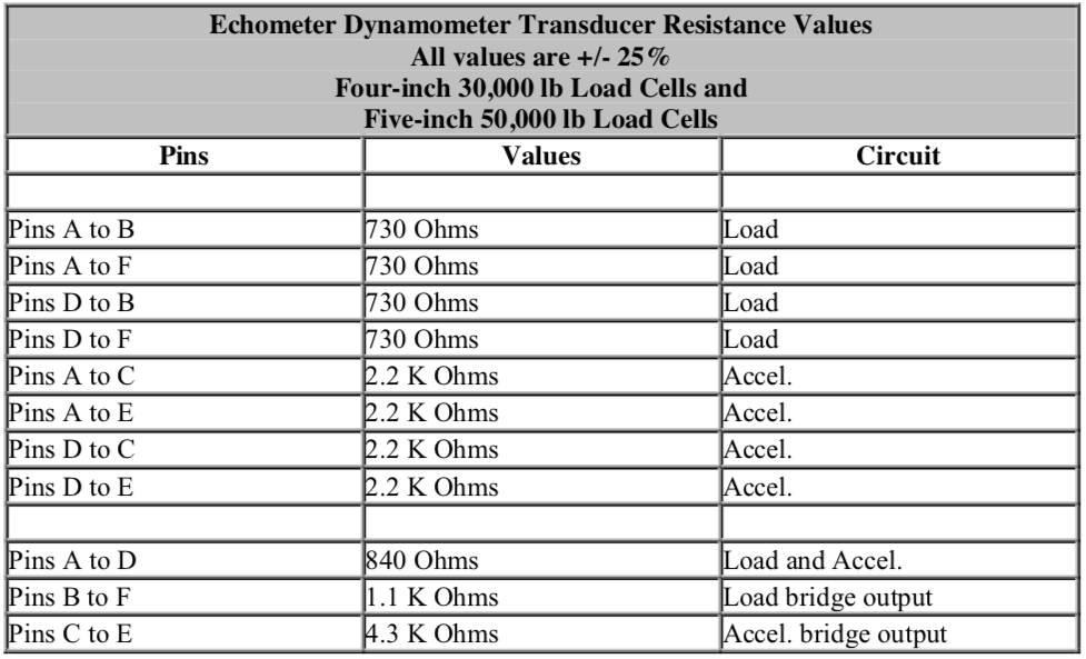
Load Cells with serial numbers HT137 through HT508 had pin "D" grounded to case when manufactured. The grounding wire from pin "D" to the case was removed, if Echometer Company has ever serviced the HT.
If the measured readings are not with-in 25% of these stated values, then you should send the Horseshoe Transducer Load Cell in to Echometer for repair.
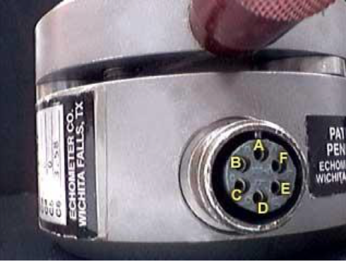
Connector pin designation for the Horseshoe Load Transducer
2) Use the Equipment Check Tab to Verify that the Well Analyzer is communicating with TWM software
Equipment Check Screen – Make sure the Laptop Computer is connected to the Echometer Well Analyzer using the proper cable. Turn on the computer, execute the TWM software, and from the Acquire Mode select the Equipment Check tab. Blue bars in the upper left hand corner of the screen indicate the battery is charged and the Well Analyzer is communicating with the Laptop computer. The user should verify that the voltage values are within the indicated limits. Discrepancies could be caused either by faulty batteries or by faulty electronics or cables and connectors.
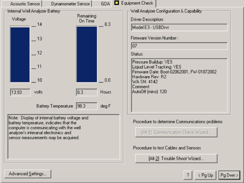
A display of internal battery voltage and battery temperature indicates that the computer is communicating with the well analyzer's internal electronics and additional testing of the horseshoe transducer may be performed using the well analyzer. Otherwise a warning message will be displayed indicating problems with communication.
3) Test the Operation of the Electronic Hardware and Cables
The most common problem is that the cables may have been damaged or the connections could be wet. Be sure there is no moisture in any of the ends of the connectors on the cables or HT. A bad cable can make the HT appear to not be functioning properly. A defective well analyzer can make the cables or HT appear to not be operating properly.
Trouble Shoot Wizard - When communication between the Well Analyzer and the Computer is operating properly, the data acquisition functions are tested using the Troubleshoot Wizard.
Testing the operation of the electronic hardware and cables is undertaken using the Trouble Shoot Wizard in the Equipment Check Tab from the SETUP module. The purpose of the utility is to quickly determine whether a hardware fault is present and in particular test that the batteries are properly charged, the transducer circuits are not shorted, the cables and connectors are not shorted or open, and that the Well Analyzer amplifiers are operating within specifications.
If the cables fail the Trouble Shoot Wizard, then you will probably need to purchase new cables.
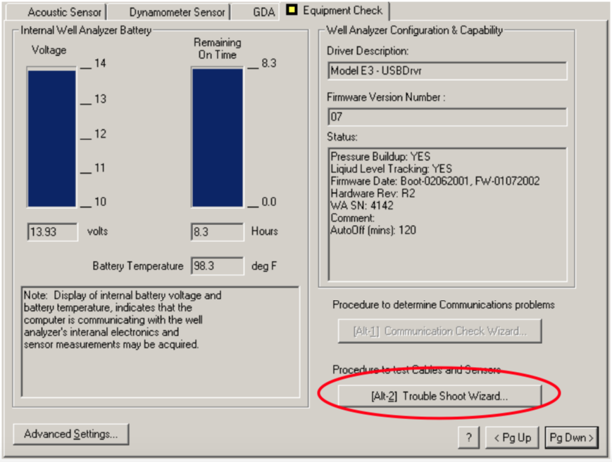
Tapping the (Alt-2) keys will begin the Trouble Shoot Wizard (Alt-2).
Voltage Check - The screen displays the existing Well Analyzer battery voltage and the voltage used to power the transducers. If the values were not within the accepted limits, the battery should be recharged and the test repeated later.
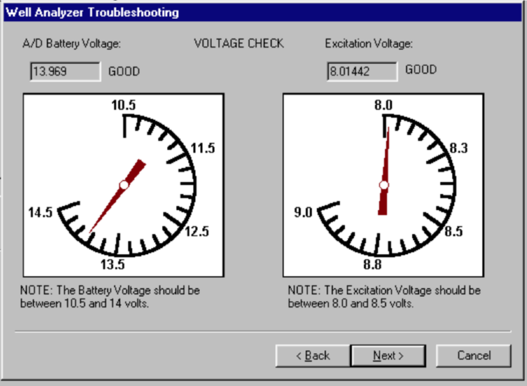
Transducer Check - If the battery voltage is within limits but the excitation voltage is not within limits or it drops significantly when the HT transducer is connected to the Well Analyzer (using the master cable) there is a good probability that the transducer is defective.
![]()
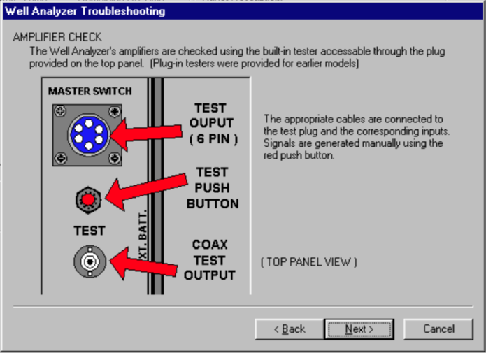
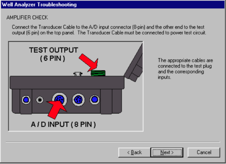
Amplifier Checks - The Well Analyzer's amplifiers are checked using the built-in tester, accessible through the plug provided on the top panel. The appropriate cables are connected to the test plug and to the corresponding inputs. Signals are generated manually using the push button. When the appropriate response is not obtained it is important to check that the failure is not due to a faulty cable or connector. Either a spare cable should be used or continuity and ground checks using an Ohmmeter should be made on the questionable cable before concluding that the amplifiers are not operating properly. The instructions presented in the following screens should be followed in order to check both the cables and the amplifiers.
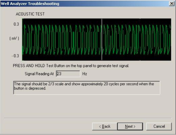
Acoustic Channel Test - This tests both the coaxial cable and the Acoustic channel amplifier. Depressing the test button should display approximately a 20 Hz frequency signal of constant amplitude, as shown in the following figure:
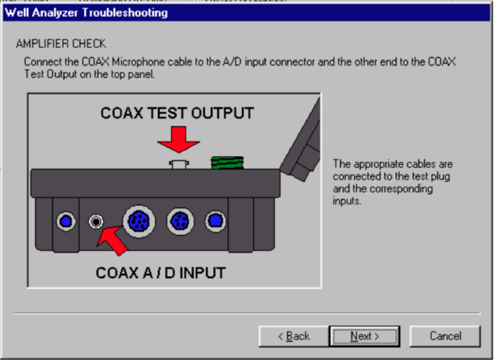
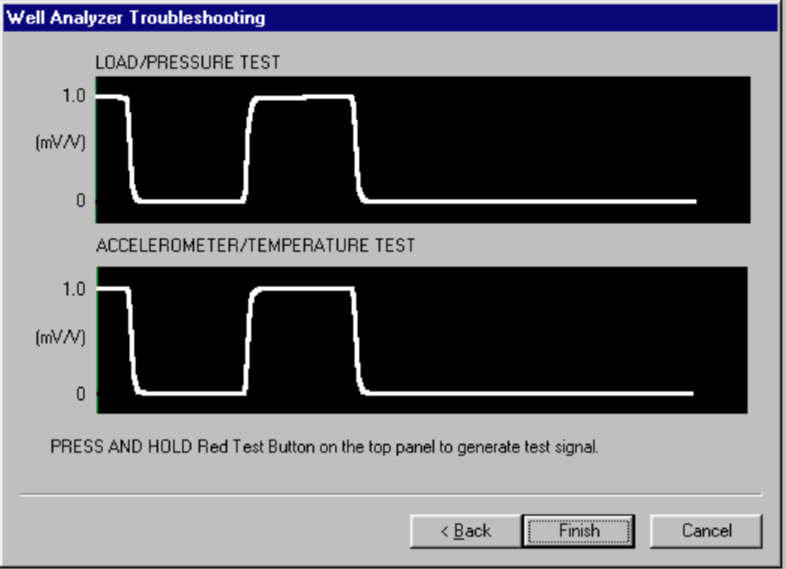
Cables, amplifiers and A/D converter check - This test verifies that the main transducer cable and the A/D converter are performing properly. The coiled cable can also be checked out using the Trouble shoot wizard, but should be tested in both un-stretched and stretched conditions. The test should be repeated using all the cables individually and connected in series so as to check the connectors as well as the cable. One last check would be to wiggle and pull on all of the connections and cables while holding down the test button. Whenever the test button is depressed the signal should increase from zero to 1 mV/v as shown below.
This completes the testing sequence. If all of the test has been completed successfully, then the TWM software, the Well Analyzer Electronics, and the cable tested are working properly. Next step is to further check out the horseshoe transducer’s operation with the TWM software.
4) Determine Dynamometer Sensor Normal Zero Offset
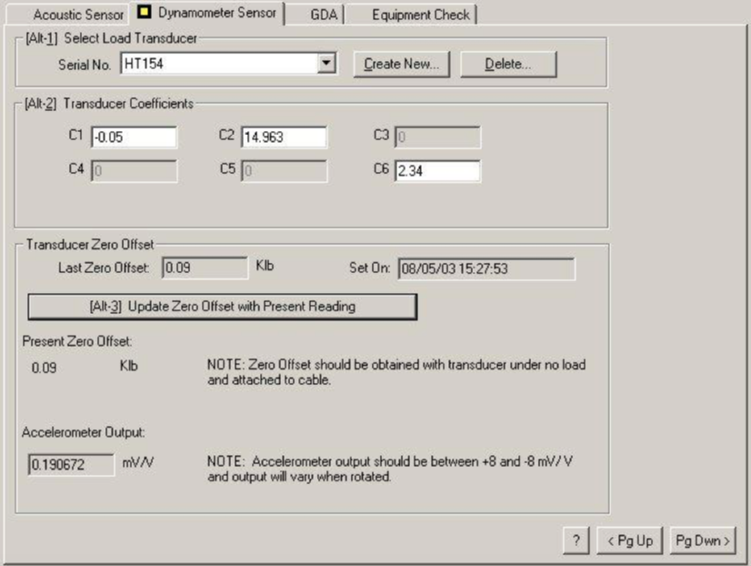
Using the well analyzer, with the TWM software running, and the dynamometer setup page open, select the proper HT serial number and verify that the proper coefficients are entered (C1, C2 and C6), then click on the “Obtain Zero Offset” button. The present output of the transducer should be a small number less than +/-1.5 Klb. A large number for the Present Zero Offset indicates a large offset load; the load cell may have been damaged and needs to be sent into Echometer for re- calibration and/or repair. The Accelerometer Output (with the HT in the upright position) should read between +8 and -8 mv/v. A high number indicates that the Accelerometer is bad or needs adjustment.
Set the Load Cell in its normal upright operating position on a flat surface. The Accelerometer Output in the lower left hand corner of the screen should display a reading near 0.0mV/V. Turn the load cell 90 degrees (on edge) and set on the flat surface of the load cell opposite the handle, then the reading should be a negative number close to the value of the C6 coefficient. Turn the load cell over and set the Load Cell upside down on its upper plate, then the reading should be about double the number read when the Load Cell was setting on its flats. This test indicates that the accelerometer is working properly and communicating with the Well Analyzer and laptop computer.
If the transducer fails to pass any of these tests, it would indicate some type of failure with-in the horseshoe transducer and the load cell transducer should be sent to Echometer for repair.
5) Simulate acquisition of a Valve Test with Dynamometer Sensor in Office
The load cell transducer should be connected to the well analyzer by the transducer cable and the coiled cable. The well analyzer should be powered on, with the TWM software operating in the Acquire mode, and the step to determine Dynamometer Sensor Zero Offset should have been completed.
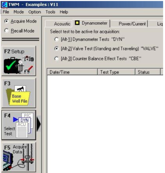
A Base Well File should be opened to perform this test. Select the “Valve Test (Standing and Traveling) “VALVE”” type of test from the Dynamometer tab.
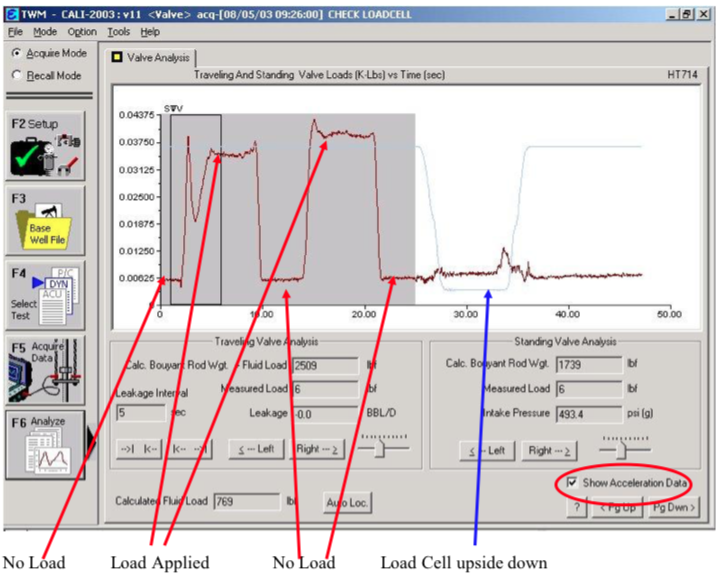
Position the Load Cell in its normal upright operating position. Press F5 to begin acquiring load data. Observe the Measured load text box on the lower right corner of the screen. The reading should be near zero.
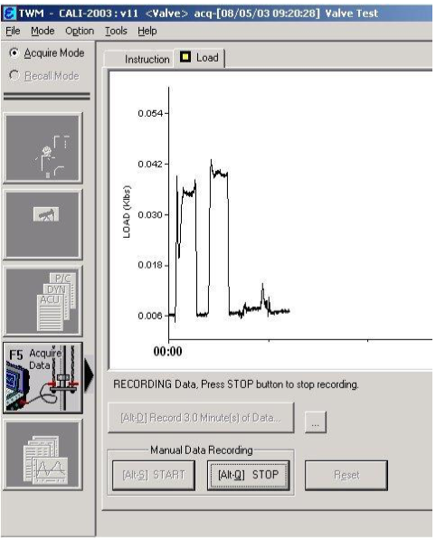
Tap the Alt-S key to begin acquiring load and acceleration data. With the load cell resting in its normal operating position, press down on the load cell with both hands cupped on the Upper Plate and apply a uniform force with a downward motion. Stop pressing for a short time. Again, press down on the load cell with both hands cupped on the Upper Plate and apply a fairly uniform downward force and then release the force. While applying the force to the load cell, observe the screen for any spikes. In the example shown to the left, units of the vertical axis is Klbs, the 1st time a force of approximately 36 lbs was applied to the load cell and the 2nd time a force of approximately 42 lbs. was applied to the load cell.
Flip the Load Cell over 180 degrees on its Upper Plate. Wait approximately 15 seconds and then rotate the load cell back to its normal mounting position.
The line will continue to travel across the bottom of the plot. Tap the Alt-Q key to stop acquiring data and then save the data.

Click the F6 button to analyze the data collected. Check the Show Acceleration Data box to display the acceleration data. The load trace should be uniformly flat when no force is being applied and should increase when load is applied. The acceleration data should be flat when the load cell is resting on the surface and quickly change when turned over.
If the test results are bad, the probable cause is some type of internal damage to the load cell. If the test results are good, then Dynamometer data can be acquired with the load cell mounted on a well.
One last check would be to wiggle and pull on all of the connections and cables while acquiring load data. If the load measurements become erratic then the cable may have a short or bad connector,