

The points to be addressed in this note is the Free Gas Handling at the Pump Intake using static bottom-hole gas separators; and a simple way to estimate free gas volume at the Pump Intake using fluids properties (PVT).
The points to be addressed in this note is the Free Gas Handling at the Pump Intake using static bottom-hole gas separators; and a simple way to estimate free gas volume at the Pump Intake using fluids properties (PVT).
One of the main reasons of bottom-hole pumps inefficient operation is the incomplete filling of liquid caused by gas interference. In this case (wells with high gas production) is recommended evaluate to settle the pump deeper, or the use of:
- Double stage pumps (SIS or circle A)
- Gas un-lockers.
- Long runs and low speed.
- The use of Packer is not recommended, since the pump would handle all the gas.
- Static bottom hole gas separators (gas anchors).
The focus for this note is the Static Bottom Hole Gas Separators (Poor Boy). It is a practical way of handling high volumes of gas at the pump intake, it uses the densities difference between the fluids (gas, liquid), which leads to a separation due to the segregation by gravity of the Liquid and Gas Phases, where the gas rise velocity is higher than oil. The static bottom gas separators use this property (the segregation by gravity) by creating a kind of labyrinth where fluids (gas, liquid) are forced to flow in a downward direction, which favors the separation between the gas and the Liquid.
Gas Separators description: At the top of the separator outer barrel or mud anchor are several openings through which the produced liquid and some gas enter to the separator, and also through which the separated gas can return to the wellbore. Inside the separator annulus there is a gas/liquid mixture with the liquid flowing down towards the dip tube suction, the dip tube is a small diameter tube inside the separator outer barrel that directs the produced fluid to the pump intake.
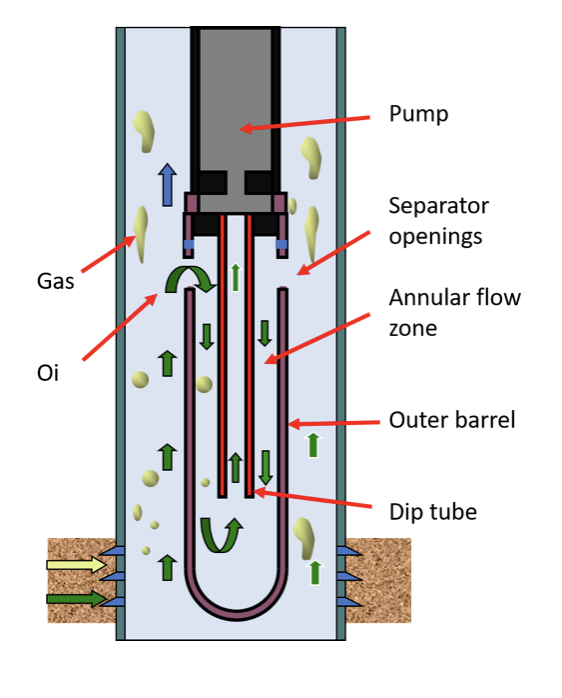
Fig 1. Simplified schematic “tubing conveyed down hole gas separator”
How fast the gas is separated from the liquid depend on the difference between the downward liquid velocity and upwards bubble slip velocity. This phenomenon is complex and considers several parameters such as: speed and direction of the different fluids, viscosity of the liquid (oil, emulsion), density difference, interfacial tension, size of the gas bubble, flow pattern.
It should be noted that Echometer Company has developed a Bottom Gas Separators Simulator (Ref 1) which allows estimating the "Separator Pump Fillage Factor". Also, show if the Gas Anchor is capable of handling gas or not.
Well, now you have a better understanding of Gas Separators works. BUT, Is free Gas at the Pump Intake? If there is, how could you estimate the amount of gas?. The second topic to cover is the Estimation of free gas volume at the pump intake.
Steps:
- Determine the amount of energy (Pressure) provide by reservoir at the pump intake.
It could be done using sensors or acoustic survey.
- Sensors.
Down hole sensors would provide a direct measurement of the pump intake pressure with a very high frequency, it’s accurate, but it is expensive.
- Acoustic survey (Liquid level measurements).
The principle in submergence level detection is based on echo detection. For this, there are equipment capable of generating a pressure pulse that create an acoustic wave, and the echoes are reflected from the connection of the pipes (tubing collars) and the liquid level. This acoustic trace allows to determine the liquid level and therefore the submergence. Once the submergence is obtained, the pressure at the bottom hole and at the intake of the pump can be determined.
The procedure is simple (Ref 4), in summary, the flowing bottom pressure (PBHP) and the PIP (Pump Intake Pressure) are calculated as the sum of the head pressure (CHP), plus the pressure generated by the gas column plus the corresponding gas free liquid column (correction for dissolved gas).
Important: The PBHP and PIP must be compared with the Reservoir Bubble Pressure (Pb), if PIP is above the Pb, that’s mean the fluid is sub-saturate, then wouldn’t be free gas at the pump inlet and a Gas Separator wouldn’t be necessary, this is true until the PIP draw below the Pb.
- Estimate formation Inflow.
- Calculate Reservoir inflow performance relationship (IPR) based on well production test.
- Estimate the maximum allowable production rate according to the IPR and avoiding production problems (coning, sand production, etc.).
- Calculate the percentage of free gas at the pump intake from the properties of the fluid.
To calculate the percentage of Free Gas would be required production test information (Liquid flow (ql), Tubing Head Pressure (THP), Casing Head Pressure (CHP), Produced Gas Oil Ratio (GORP), Water Percentage (%WyS). Additionally, PVT test data is required (ºAPI, Gas in solution (Rs), Gas specific gravity (γg), Oil specific gravity (γp), Oil Formation Volume Factor (Bo @ PIP), Gas Formation Volume Factor (Bg @ PIP), Factor deviation of Gas (Z), Solution Gas-Oil Ratio at PIP (Rs @ PIP)). And a Gas Separator Mechanical Efficiency of the must be definite.
Calculations:
1. Oil Gas Ratio once the gas anchor is installed (GOR anchor):

*A new Gas-Oil Ratio is generated due to part of the gas is diverted to the tubing casing annulus.
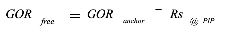
2. Oil Gas Ratio Free at Pump Conditions
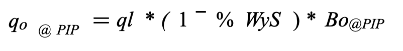
3. Oil rates (qo), Water (qw), Gas (qg), from the P.V.T properties to pump conditions (@ PIP).
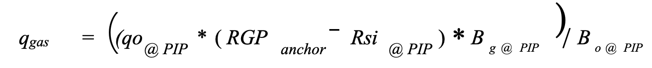
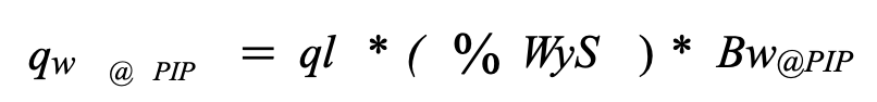
* Units of: qo, qw, qgas are bbls/day.
4. Total flow rate (qT).
5. Fraction of each component.
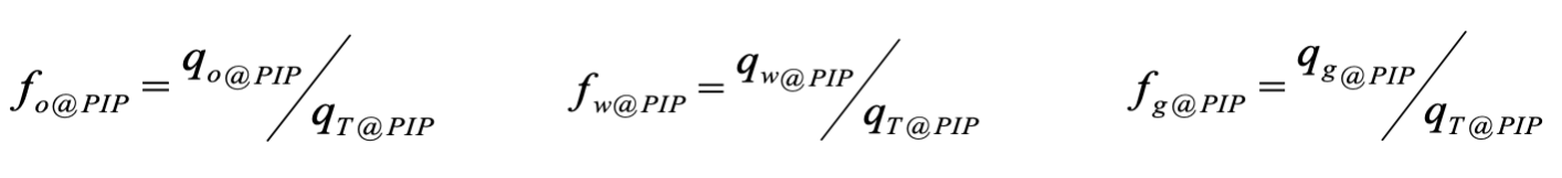
* All calculations and data are referred to the pump intake level (@ PIP)
With this procedure can be calculate the amount of free gas at the pump intake in different scenarios; without using the gas anchor or using it with various mechanical efficiency percentage.
Conclusions:
- The use of a static bottom hole gas separator turns out to be a practical and efficient way to handle the free gas at the pump inlet. Removing free gas allows to increase Oil production and improve system efficiency
Various technical articles (Ref 1, 5) present different forms to simulate the performance and optimize the design of these equipments.
- It is important to know the free gas volume at pump conditions to predict the pump performance. Therefore, a simple procedure is presented based on PVT analysis information.
References:
- J. N. McCoy, Ken Skinner and O. Lynn Rowlan, Echometer Company, Kyle Marshall, Capsher Technology, Tony Podio, Down-Hole Gas Separator Performance Simulation Software
- Walker, C.P.: “Determination of Fluid Level in Oil Wells by the Pressure-wave Echo Method” AIME Transactions April 1937.
- McCoy et al.: “Acoustic Determination of Producing Bottom Hole Pressure” paper SPE 14254 presented at the 1985 SPE Annual Technical Conference and Exhibition, Las Vegas NV.
- Robles, J. and A. L. Podio, “Effect of Free Gas and Downhole Gas Separation Efficiency on the Volumetric Efficiency of Sucker Rod Pumps and Progressing Cavity Pumps,” Proceedings of the 43rd Annual Meeting of the SWPSC, 1996.
- Bohorquez, R., Ananaba, V., Alabi, O., Podio, A. L., Lisigurski, O. and Guzman, M.: 2009, “Laboratory Testing of Downhole Gas Separators”, SPE Production and Operations, Volume 24, Number 4, pp.499-509.